Overview
I have created a gravity-powered marble logic gate that can compute logic using marbles rather than electricity, which could be used to create an automatic marble computer. I used Fusion 360 to design all the 3D components and 3D printed them using PLA plastic.
My logic gate has 2 inputs and 3 outputs and is ‘universal’, meaning it can be used to compute any possible logical function. I have designed mechanisms for the gate to reset its state automatically, allowing it to be used repeatedly without human intervention, unlike existing marble-logic gate systems.
I encountered many challenges during the design and printing process, such as printed mechanisms that didn’t move or were unreliable. However, after many iterations of designing, printing, and testing, I managed to create a functional marble logic gate.
Overall, I learnt a lot throughout this project. It has given me a greater understanding of how low-level logic works, how to use Fusion 360 to parametrically design 3D mechanical components that can fit together, and how to print them on an FDM 3D printer.
What are logic gates?
Logical gates are low-level components that process data and are the building blocks of any modern computer. They are used extensively in digital circuits such as the CPU and GPU to perform functions including arithmetic (e.g. addition, subtraction, multiplication, and division) on binary data and many other functions.
In essence, a circuit constructed using logic gates is a function which maps a set of binary inputs to a set of binary outputs.
For example, in a 2-bit logic gate, there are 4 possible sets of binary inputs: {0, 0}, {0, 1}, {1, 0}, {1, 1}. The number of possible inputs is always 2 to the power of the number of inputs to the logic function.
One simple logic gate is the 2-bit AND gate, in which a 0 will be outputted in all cases except when both inputs are 1. This mapping is usually represented as a truth table:
| A | B | A AND B |
|---|---|---|
| 0 | 0 | 0 |
| 0 | 1 | 0 |
| 1 | 0 | 0 |
| 1 | 1 | 1 |
Simple logical gates such as AND, OR and NOT can be combined to perform more complex Boolean functions.
What has been done before?
There are many great examples that demonstrate unconventional logic gates that could (in theory) be scaled to build an entire computer. I have listed a few interesting examples, but there are many more.
Domino Gates
In 2014, Matt Parker (From Stand Up Maths) used dominoes to construct AND, and XOR logic gates, where a 1 is represented by a stream of falling dominoes which cascade through the circuit and interact with other rows of dominoes. His team arranged 10,000 dominoes to construct a logical circuit which combines domino logic gates to add binary values.
Water-Based Gates
In 2021, Steve Mould and Matt Parker created a water calculator. As part of this, they created an AND gate using a greedy-cup siphon, in which two input pipes of water are channelled into the siphon. A binary 1 is represented as a set volume of water, so if two water streams are combined into the siphon at the same time, the siphon will overflow and drain out all of the water. They also configure the siphons to operate as XOR gates. Finally, they combine XOR and AND gates to construct a small water calculator that can add 4 binary values.
Marble-Based Gates
There are numerous examples of marble-based calculators and logic gates that have been created. I have listed some of them below:
The “Digi-Comp II” is a mechanical computer invented by John Godfrey in 1965 and uses marbles, switches, and a physical board to process operations on binary values. The switches have to be manually configured to set a particular operation, and the result is represented using the direction of each switch. It has been adapted many times, and this video provides a demonstration.
Lapinozz constructed logic gates using cardboard and marbles to create a marble calculator. This is a great example which demonstrates that truly any material can be used to construct a logic gate. This design is interesting in that no switches are used, and unlike other marble computers, the binary values themselves are represented using marbles.
A group of students used plywood to create marble-based logic gates, including AND, XOR and a Full Adder. This design is similar to the previous in that the marbles themselves are used to represent the binary values.
Self-resetting Logic
However, as far as I know, none of these previous gates automatically reset themselves. The reason this is important is that in computers, the same logic gates would need to be used over and over again. Ideally, the logic gate should reset its state automatically following a computation so that the computer can operate independently.
For example, after a domino computer logic gate has been used, you would have to manually reset each individual domino before it can be used again.
In the water-based computer, you have to tip the whole system upside down in order to reset the gates.
In the marble-based “Digi-Comp II”, you have to reset the switches manually following a computation to use it again.
In both of the other marble-based gates presented, marbles will be left in the system and need to be manually removed before the gates can be reused.
Moreover, many previous work aims to reconstruct traditional logical gates such as AND, OR, XOR individually. I imagine they do this because these simple gates can be combined to produce any logical gate and are also the ones commonly implemented. However, this can add additional complexity as different designs and mechanisms are needed for each gate.
Designing the Marble Logic Gate
Initial Design
Initially, when I started this project, I never intended on creating a universal logic gate – my goal was inspired by previous marble-based gates and I wanted to create individual AND, OR and NOT gates that could eventually be combined to build an automatic marble-based computer.
I started with the AND gate, which seemed like the simplest gate to create. I thought maybe one marble could hit a switch, which would change the path of the second marble, which if present, would fall through to the output channel. One of my initial designs looked something like this:
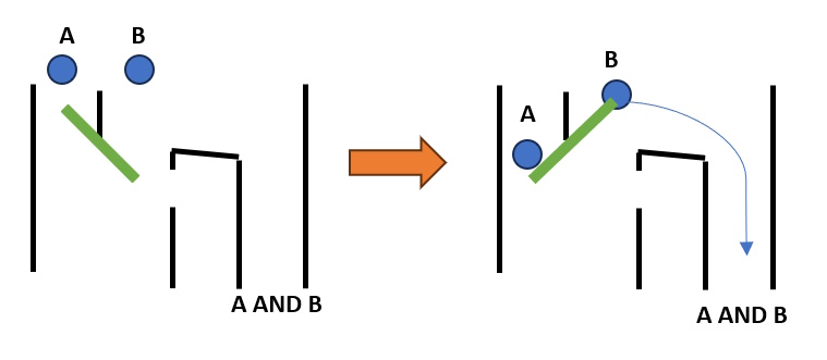
In this design, a marble only arrives in the rightmost channel if there is a marble in channel B and one in channel A. If there is a marble in channel A, it will ‘activate’ the switch and direct marble B to the rightmost channel; otherwise, the marble in channel B would simply fall through. This circuit was my first design of the AND gate.
This design avoids the problem of previous marble-based gates, where marbles become stuck inside the system and must be removed; however, there are a couple of issues with this design. Firstly, whenever the switch is activated, it would need to somehow reset itself automatically so that the logic gate can be reused. Secondly, this logic gate would be very sensitive to timings – what would happen if the marble at channel A arrived slightly later than the one at channel B? In that case, the marble at channel B may not be directed to the rightmost channel, and the logic gate would output a 0 even though both marbles are present.
Solving the Timing Issue
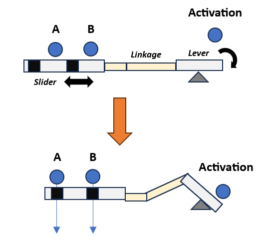
To solve the timing issue, I designed a component that could hold the marbles on a slider temporarily until the logic gate was ready to be used. The slider can be activated by another marble that will release both of the inputs at the same time. To accomplish this, I used a lever and a linkage mechanism to convert the rotational motion of the falling activation marble to move the slider linearly. The slider has holes to allow the marbles A and B to fall together when the slider is moved a certain distance.
Designing the Dropper in 3D
As I wanted to create a physical logic gate, I designed a dropper mechanism using FreeCAD so that I could print it using my 3D printer.
The linkage mechanism is made up of two hinges that connect the lever to the slider. When designing this component, there are many variables which affect how sensitive the linkage is and how much the slider will move. To find appropriate values, such as the length of the linkage components and the position of the fulcrum, I created a Desmos plot which calculates how much the slider will move depending on the angle of the slider and other factors.
Desmos animation of the linkage and slider mechanisms
An early design of a ‘Dropping mechanism’ modelled in FreeCAD
When printing these designs, I encountered several problems. I had to experiment with various parameters, such as the clearance between the slider and the walls, as initially, the 3D-printed slider would not slide reliably due to friction. Another problem was that the slider would not return to its original location after it had been activated, which is a problem as the mechanism should reset itself. I experimented with different designs and made modifications to improve this.
At times, I also experienced issues with FreeCAD itself as it was a bit buggy, so I instead used Fusion 360 to create future designs.
Eventually, after many iterations of designing, printing, and testing, I managed to create a reliable working ‘Dropping mechanism’. This is still not the logic gate yet, but it is a crucial component to ensure that the inputs will arrive at the same time. After creating the first working implementation, I made improvements to ‘miniaturise’ the design as much as is reasonably possible, so that it was faster to print and more reliable.
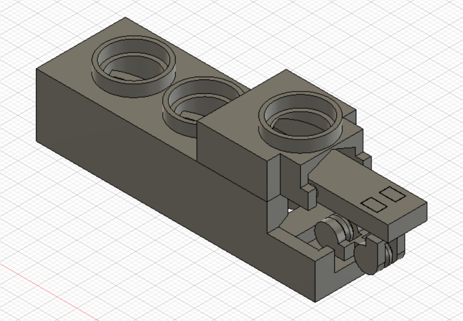
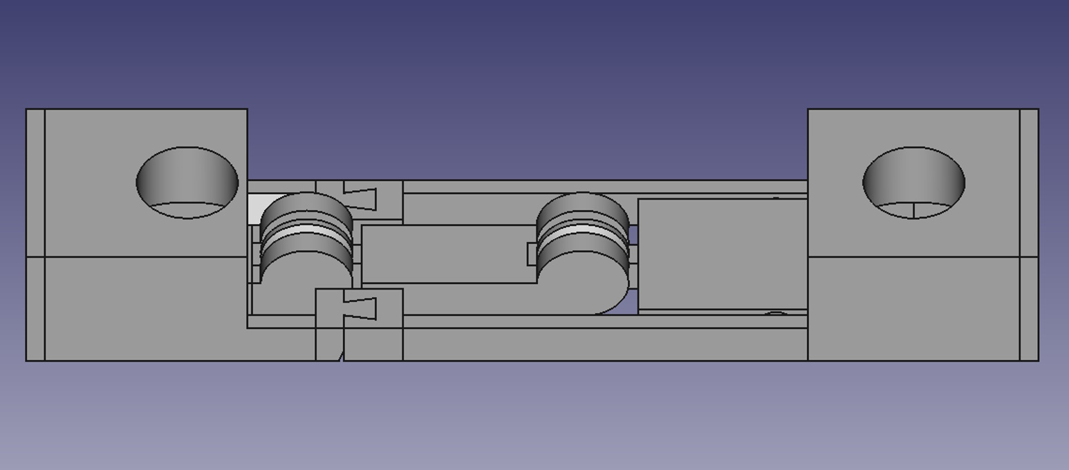
My current Fusion 360 design for the ‘Dropping mechanism’
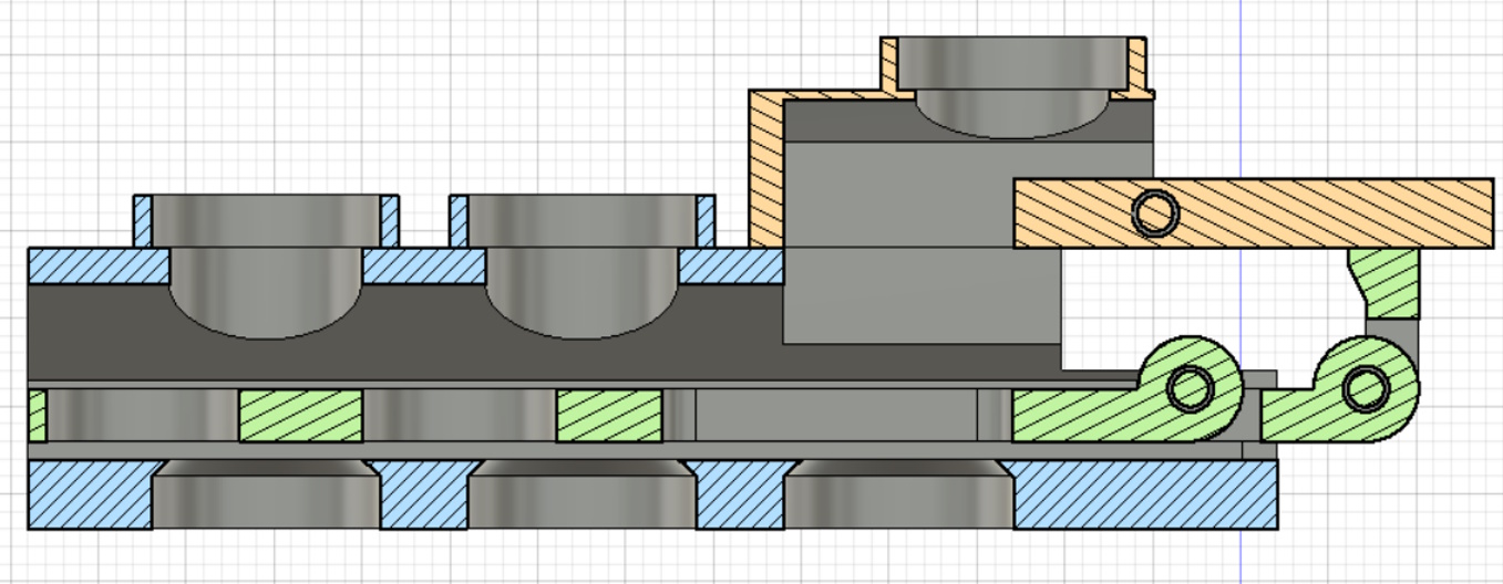
A cross section of the design
I have designed the dropping mechanism to be printed in three parts, as shown by the different colours above. These parts can be fitted together to construct the dropper. When a marble is placed at the top right, it will activate the mechanism.
Designing the Logic Gate in 3D
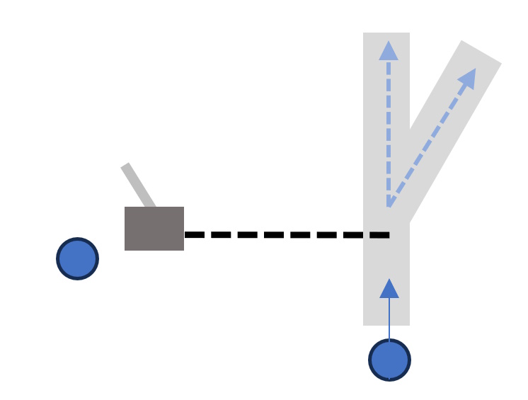
To design the logic gate, I used the same slider, linkage and lever mechanisms used for the ‘Dropper’. However, I made some slight modifications to the slider so that it acts like a marble switch. If there is no marble activating the slider, then the other marble will be directed by the slider to the left output. If there is a marble activating the slider, then the other marble will be diverted to the right output.
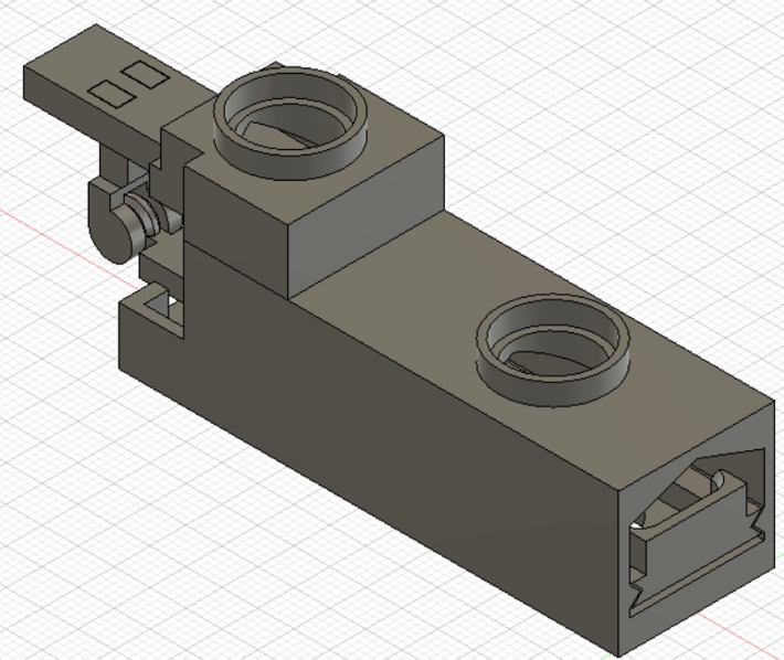
My current Fusion 360 design for the Logic Gate
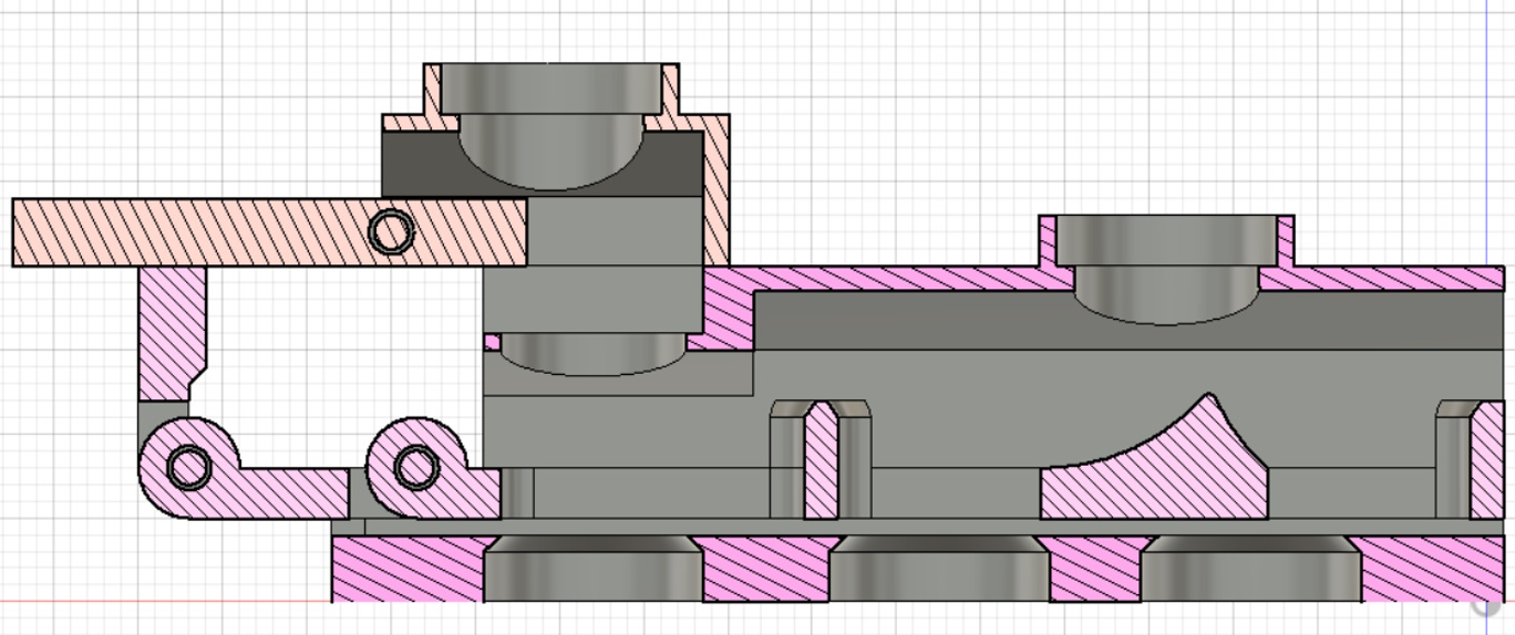
A cross section of the design
This component actually implements the logic gate. In effect, how this operates is similar to how a train could be diverted onto a different track when a switch is activated. The marble that is placed on the lever momentarily ‘switches’ the track and diverts the other marble to a different output channel:
Putting Everything Together - The Self-Resetting Marble Gate
I have designed all of the components so that they can fit together to form a working, self-resetting marble logic gate, and I have created pipes to route the marbles from the dropper to the logic gate:

My current Fusion 360 design for the Self-Resetting Marble Logic Gate
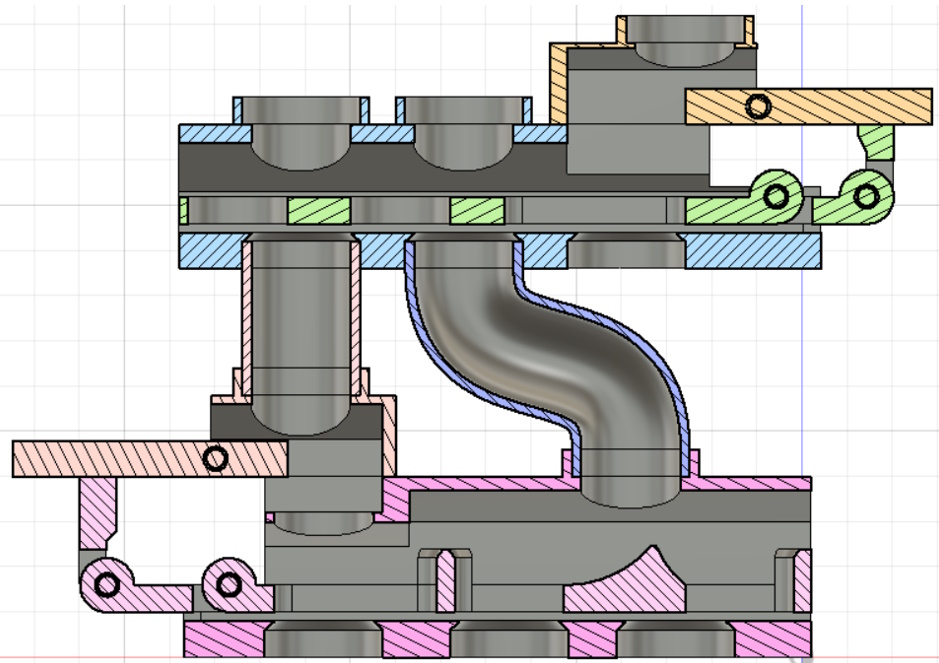
A cross section of the design
The whole design was printed using 8 individual parts (including the 2 pipes) using an Ender 3 V2 3D printer. This design can reliably perform as a self-resetting logic gate; however, the design needs to be refined further. One issue is that the clearance between the pipes and the connectors is too high, which can cause them to decouple. I also need to modify the design so that an additional pipe can be added to route the activating marble from the dropper.
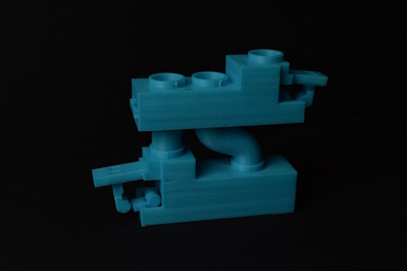
The 3D printed Marble Logic Gate
What can this Marble Logic Gate do?
When I started this project, my goal was to build a resettable AND gate, but I have since realised that my Marble Logic Gate is a ‘universal’ logical gate. This means that it can be used to construct any possible logical function (including AND, OR, NOT, XOR, etc.).
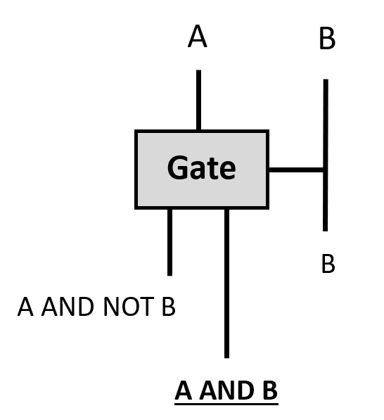
This gate has 2 inputs and 3 outputs. Below is the truth table of the Marble Logic Gate:
| A | B | A AND B | A AND NOT B | B |
|---|---|---|---|---|
| 0 | 0 | 0 | 0 | 0 |
| 0 | 1 | 0 | 0 | 1 |
| 1 | 0 | 0 | 1 | 0 |
| 1 | 1 | 1 | 0 | 1 |
Below are circuit diagrams showing how AND, OR, NOT and XOR logic gates can be constructed using the Marble Logic Gate. When a line points horizontally on the side of the gate, that means that it is ‘switching’ the logic gate.
AND Gate
A single marble gate can implement AND:
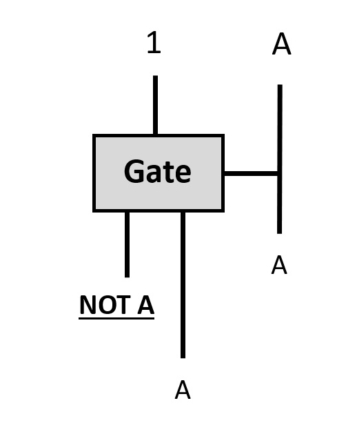
NOT Gate
A single marble gate can implement NOT. The ‘1’ represents a constant, where there will always be a marble in this location:
OR Gate
A single marble gate can implement OR, when two of the outputs of the gate are merged together:
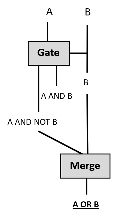
Technically, you do not have to use merge to get the OR gate; you could instead combine AND and NOT gates using multiple Marble Logic Gates, but it is easier to use merge.
XOR Gate
Two marble gates can be combined to implement XOR, and two of the outputs of the gate are merged together:

Summary
In this project, I have designed and created a self-resetting universal marble logic gate. I mainly used Fusion 360 to design the components and printed them using an FDM 3D printer with PLA. I encountered many problems throughout this project, and many failed designs and prints were created in the process that I have not included here.
Overall, I enjoyed working on every aspect of the project, from the logical designs of creating a universal gate, which helped improve my knowledge of Boolean Algebra, the mathematical modelling, and learning how to design models using parametric 3D CAD software that can be printed using a 3D printer.
There is so much room to extend this project, which I plan to do in the future, such as combining multiple logic gates to build a binary adder or even creating a simple marble computer.